Overview
A driverless vehicle loads ingot bundles and drum pallets into cargo racks, which are weighed, locked and tagged.
Area 17 packs each export payload into a reusable steel rack: a 1,923 kg ingot bundle or a pallet of four residue drums. The ship's load plan needs the true mass and centre of gravity of every rack, so both are measured.
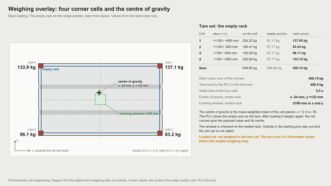
A driverless vehicle takes each payload at the end of its line and pushes it into an empty rack. Four load cells (weight sensors) under the rack weigh it. Four bolts then lock the payload, and the rack moves on to the launch yard.
Process steps
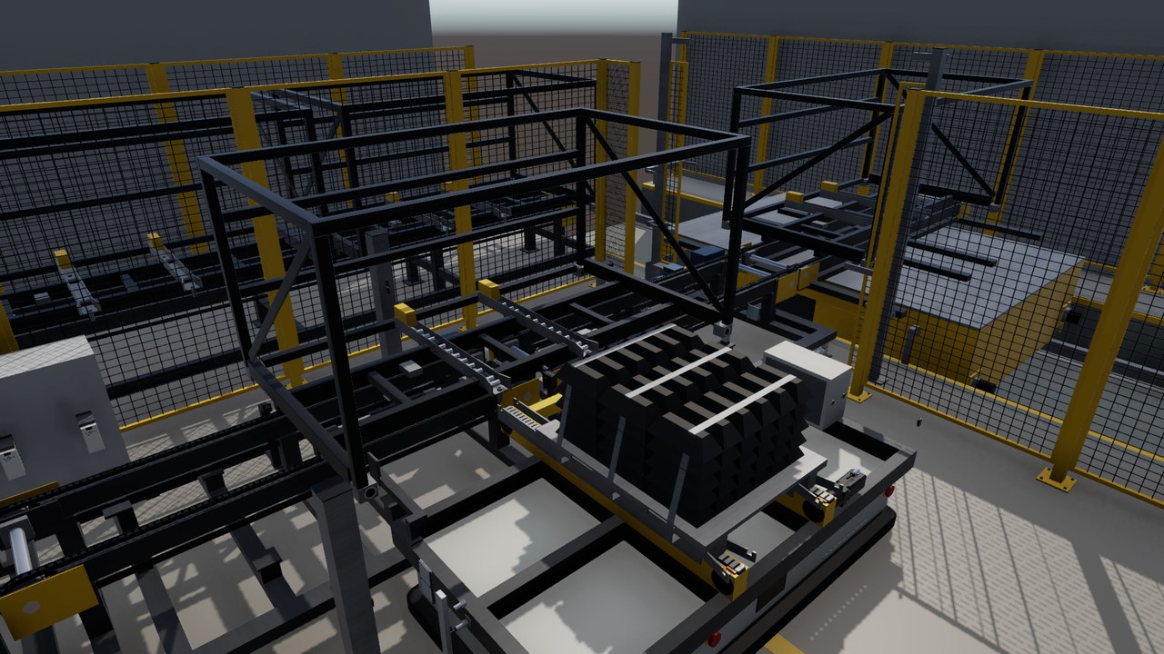
- The weigh section takes an empty rack from the rail cart and weighs it.
- The driverless vehicle picks up a bundle or drum pallet at its line conveyor.
- In about 2 min, it brings the payload and pushes it into the rack.
- The scale weighs the loaded rack and checks mass and centre of gravity.
- Four cylinders push the lashing bolts up and lock the payload in the rack.
- The rack tag gets its record, and the rack moves onto the rail cart.
The line in the twin
Turning view
Specifications
The equipment list
| Unit | Function | Key data |
|---|---|---|
| Driverless vehicle | Carries one bundle or drum pallet from line to rack. | Up to 3 t, 1.0 m/s loaded, ±5 mm positioning |
| Chain conveyor on the vehicle | Lifts the payload and pushes it into the rack. | Lift 100 mm, push at 0.1 m/s |
| Chain weigh section with corner scale | Weighs each rack and moves it to the rail cart. | Four 1 t load cells, weighing in 5 s |
| Lashing cylinders | Push the four rack bolts up into the payload. | 4 air cylinders, 483 N each at 6 bar |
| Radio tag reader and rack tag | Reads the rack number and writes the rack record. | Write and read back in 2 s |
| Reusable cargo rack | Steel frame that carries one payload into the ship. | 2.4 x 1.4 x 1.2 m, 450 kg empty |
Links lead to the makers' public product pages and are given for reference only. This site is independent work, not affiliated with, sponsored or endorsed by any manufacturer. The makers are responsible for the content of their pages. Trademarks belong to their owners.
Control and safety
- The line and the vehicle are designed with their own PLC (industrial control computer), linked by radio.
- No safety function uses the radio: scanners and emergency stops act through a safety controller.
- A wrong mass or centre of gravity holds the rack, and eight fault test cases are specified.
- The single devices are modelled from their datasheets and tested against the PLC.
The hand-overs
| From | Bundles come from Area 15, drum pallets from Area 16 and empty racks by rail cart. |
| To | Weighed and tagged racks go by rail cart to Area 18 (launch yard), 3.38 per hour. |
The devices and signals
- Line PLC: 23 input and output terminals in 3 I/O stations.
- 81 line signals: 29 digital inputs, 16 digital outputs, 7 analog (4 of them load cell bridges), 15 safe inputs, 12 safe outputs and 2 others.
- Vehicle PLC of the driverless vehicle: 6 terminals and 28 signals, with 1 servo drive for the top chain.
- 3 conveyor drives on hard-wired signals.
- Safety devices: 2 emergency stop stations and 5 safety laser scanners. The vehicle has its own scanners, emergency stops and bumper.
- Process sensors: a corner scale on 4 load cells, a radio tag read head and 4 lashing cylinders with position sensors.
The safety functions
- Scanners at the loading place and at the cart station: a person in the field stops the chain conveyors by safe torque off (stop category 0).
- Field switching: the second field leaves out only the docked vehicle and holds the conveyors in safe torque off. After an entry, a restart needs a reset.
- The twin found that the conveyors only coast to a stop (3.22 s), so the field would need 6.5 m. The conveyors get a safe brake.
- No safety function runs over the radio. The vehicle protects its own hazards.
- Target: performance level d, category 3, a target and not a claim.
The tests run in the twin
- Scene built on 2026-10-25. PLC program written the same day.
- Its safety logic was tested on a model: 2,048 input combinations, 300 cold starts, 55 sensor fault runs and a random walk of 3,003 s. 0 failures.
- The program review asked for 2 blocking and 3 major fixes. That round comes next, then the first run against the 3D scene.
- Eight fault tests are defined, among them a radio loss of 30 s and a broken sensor wire.
About this page
In the scenario, this hall on 16 Psyche packs the export metal into cargo racks for the ships bound for Earth.
Real devices, built from real data
Every machine and device in this twin is a real industrial product from the makers' catalogues. They range from sensors, valves and drives to safety scanners, load cells and RFID readers. Each model is built from the product's published data: dimensions, sensing ranges, signals, rated values, parameters and timing.
The PLC programs use the devices' real interfaces and parameters. Before any hardware existed, the twin found hundreds of faults in the plant design and the programs. So a real commissioning would need fine tuning, not a redesign.