Overview
Two crushers, a screen and a magnetic drum free the metal from 10 t/h of raw ore.
Area 11 frees the natural iron-nickel metal from the rock, with no chemistry. The feed is regolith, loose surface rock with 65 wt % metal. The rock breaks in the crushers, but the metal only flattens. Below 12 mm, most metal grains are free.
A feeder draws ore from a 30 m³ bin into the jaw crusher. A screen cuts the stream at 40, 12 and 3 mm. A magnetic drum takes out the metal nuggets. The cone crusher breaks the coarse rock and returns it to the screen.
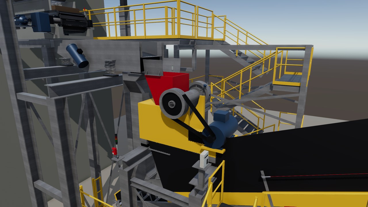
Process steps
- A loader dumps raw ore through a 200 mm grid into the feed bin.
- The feeder draws ore in pulses, and a belt scale holds 10 t/h.
- The jaw crusher breaks the large rocks, and the metal passes through flattened.
- The screen splits the stream at 40, 12 and 3 mm.
- The drum takes out the nuggets, and the cone crusher re-crushes the coarse rock.
- Belts carry two fine fractions to magnetic separation and the nuggets to melting.
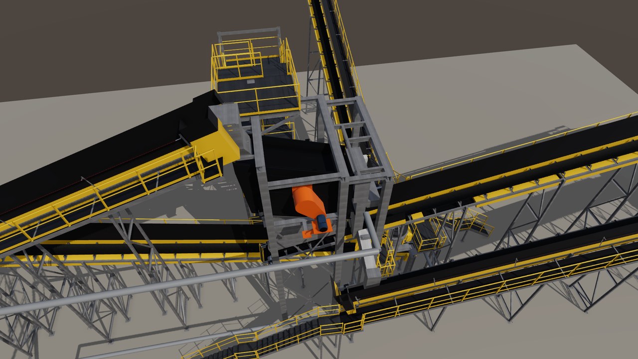
The line in the twin
Turning view
Specifications
The equipment list
| Unit | Function | Key data |
|---|---|---|
| Feed bin and apron feeder | Stores the ore, and a steel-pan conveyor draws it out. | 30 m³ bin, 3.5 s pulse every 30 s |
| Jaw crusher | Breaks the large rocks. The metal passes through flattened. | 40 mm gap, 6.5 t/h, 75 kW |
| Main belt with belt scale | Lifts ore to the screen and weighs the fresh feed. | 650 mm belt, 1.6 m/s, 13.0 t/h |
| Three-deck screen | Splits the stream into three sizes and removes the dust. | 6 m², cuts at 40, 12 and 3 mm |
| Magnetic drum | Pulls the metal nuggets out before the cone crusher. | Ø 500 x 1,000 mm, 1.50 t/h nuggets out |
| Cone crusher | Crushes the coarse rock again in a closed loop. | 12 mm gap, 3.00 t/h loop, 90 kW |
Links lead to the makers' public product pages and are given for reference only. This site is independent work, not affiliated with, sponsored or endorsed by any manufacturer. The makers are responsible for the content of their pages. Trademarks belong to their owners.
Control and safety
- The start sequence is defined against the flow, so the last unit starts first, after a horn warning.
- Each unit runs only while the next one runs, so a blocked chute stops the feed without spill.
- Emergency stops and safety ropes cut the motor power, and six fault test cases are specified.
- The single devices are modelled from the datasheet and tested against the PLC (control computer).
The hand-overs
| From | Raw regolith from the mine: 10.00 t/h, dry, 65 wt % metal. |
| To | Two size fractions (5.20 and 3.20 t/h) to magnetic separation, 1.50 t/h of nuggets to melting. |
The devices and signals
- One line PLC with 26 input and output terminals in 3 I/O stations.
- 84 signals: 21 digital inputs, 15 digital outputs, 9 analog, 14 safe inputs, 4 safe outputs, 8 speed counters, 6 digital sensor ports and 7 drive links.
- 12 variable speed drives: 7 on the fieldbus, 5 on hard-wired signals.
- Safety devices: 1 emergency stop station and 6 pull-rope emergency stop switches along the belts.
- Process sensors: 1 belt scale, 3 radar level sensors, 3 vibration sensors, 2 temperature sensors, 12 speed and chute sensors, 5 belt drift switches.
The safety functions
- Emergency stop at the operator station and pull-rope switches along every walkway. Each switch has its own safe input pair, so one fault cannot hide another.
- Safe torque off in two zones: 5 drives in zone 1, 7 drives in zone 2. Stop category 0: the crushers coast down.
- A reset never starts a machine. A new start comes only after the horn warning.
- Fixed guards close every belt nip: 2,945 guard sheets in the scene. Every sheet removed in routine work weighs 15 kg or less.
- Target: performance level d. It is a target, not a claim. The twin's safety logic is a test model.
The tests run in the twin
- Closed on 2026-10-15 after the acceptance run: 209 test rows, 206 passed, 0 failed, 3 not run by design.
- Six fault tests: emergency stop at full rate, a blocked chute, a failed belt scale, a broken safety wire, a drive trip and a full bin downstream. 66 of 66 checks passed.
- 12 of 12 emergency stop rows passed. The feed held 9.85 to 10.0 t/h.
- This area added 20 entries to the twin's findings log.
In the process chain
About this page
In the scenario, this is the first area of the plant on 16 Psyche, fed with raw ore from the mine.
Real devices, built from real data
Every machine and device in this twin is a real industrial product from the makers' catalogues. They range from sensors, valves and drives to safety scanners, load cells and RFID readers. Each model is built from the product's published data: dimensions, sensing ranges, signals, rated values, parameters and timing.
The PLC programs use the devices' real interfaces and parameters. Before any hardware existed, the twin found hundreds of faults in the plant design and the programs. So a real commissioning would need fine tuning, not a redesign.